This is a suggested walkthrough you can recreate in the editor. The aim is to show how system and system component modelling complements activity modelling when equipment changes over time. In this example, imagine a packaging cell with a controller cabinet, a vision station, and a tool mount that can host different pieces of equipment through the life of the cell.
The point of the exercise is not simply to draw the structure. It is to make later activities testable against that structure so you can see whether inspection, replacement, or commissioning work refers to equipment that is actually present at the time shown on the diagram.
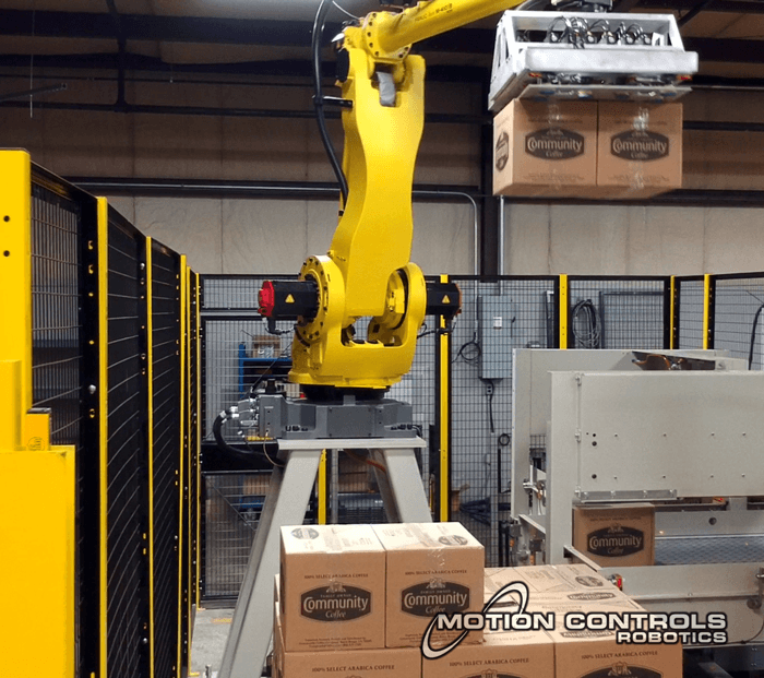
Image courtesy of Motion Controls Robotics
Step 1: Define the system
Create a system called Packaging Cell A and give it a lifespan that represents the period you want to analyse. This creates the parent entity for the rest of the structure.
At this stage it is helpful to decide the level of detail you need. If decisions are made against the whole cell, model the whole cell as a system. If the decisions are really about one skidded subsystem or one cabinet, create that as the system instead.

Step 2: Define the slots
Add system components such as Main Controller Slot, Vision Camera Mount, and Tool Head Position. Each one should be made a component of Packaging Cell A and given bounds that describe when that slot exists in the model.
This is the structural part of the model. The component is not the device occupying that position. It is the named place in the system where a device may be fused. That distinction is what allows you to replace equipment later without losing the slot identity.

Step 3: Fuse equipment into component slots over time
Create ordinary individuals for the equipment itself, for example PLC Unit 01, Camera Unit 01, and later Camera Unit 02. Reopen those individuals and add installation rows (the editor calls these fusions “installations”) that place them into the relevant component slots for the correct periods. For this worked example, install Camera Unit 01 into Vision Camera Mount from 0 to 5, then install Camera Unit 02 into the same mount from 6 to 10. Install PLC Unit 01 into Main Controller Slotfrom 0 to infinity.
This gives you one clearly bounded replacement and one continuously installed item for comparison. The editor will reject overlapping occupancy of the same slot, so the camera handover stays explicit, while the always-installed PLC gives you a participant that should stay valid across the full test period.

Step 4: Model activities against the installed equipment
This step is where the structure model starts doing useful checking. Create four test activities. Because you define the start and end times and select participants within the same form, you can immediately see whether the relevant installations are available to pick for those specific time ranges.
For this example, try creating Inspect Vision Station A from 1 to 4. In the participant list, the installation for Camera Unit 01 should appear because it is installed from 0 to 5. Then try creating Camera Gap Check from 5 to 6. For that activity, neither camera installation will appear, because the activity falls into the handover gap between the two installations. Next, try Inspect Vision Station B from 7 to 9, where the installation for Camera Unit 02 should appear because it is installed from 6 to 10. Finally, try PLC Check from 2 to 8. The installation for PLC Unit 01 should appear because it is installed in Main Controller Slot from 0 to infinity. The practical test is simply whether the right installation is available to choose.

Load the full example
You can load the complete packaging cell setup directly in the editor by choosing Packaging Cell from the examples menu. This will let you explore the system hierarchy, individuals, and the validation checks in real time.
The same structural approach can be applied to many other scenarios where equipment changes over time, such as an air-handling unit with replaceable filters, a power cabinet with swapped modules, or a maintenance bay where tools and fixtures occupy specific stations across different jobs.